Before starting to build and test the 500 watt HF linear amplifier, I decided to consolidate and clean up the enhancements that I had made to the Ten Tec Omni D. I had made these enhancements over time a little bit at a time and each of them housed in its own project box arranged on the desk. It clutters the desktop, looks ugly, and the scattered cables are sensitive to and a source of RFI.
This is also a smaller project and it give me the opportunity to test some of the processes and skills I will be using to build the linear witch is more cvomplex.
Here is a list of the items that I have built overtime and their function:
- Keyer: Ten Tec Omni D is a 1980s vintage radio and does not have a keyer. It is made to work with a straight key only. So, I have added a keyer function to it. It is a simple Reed relay driven by the Raspberry Pi running my Stationmaster software (more on this later).
- Tutor: To practice morse code, I built a tutor. I can send code and have it be displayed on the screen. The speed and spacing are controlled by the Stationmaster software. The Raspberry Pi is not fast enough to generate a 500 Hz to 1 KHz tone (or it can't do so going through the Go library and I/O drivers). So, the Raspberry Pi keys a bistable multivibrator and the audio is played through a small speaker driven by a class A one transistor amplifier.
- The keyer and tutor are housed in one project box and it is powered by a wall wart.
- The Ten Tec VFO is not very accurate or stable. So, I have replaced it with an AD9850 function generator with built in low pass filter from Nooelec
- I have also routed the Ten Tec band select switch to the VFO project box and use it in two ways. One is to inform the software driving the function generator what frequency range to generate. The other is to pre-populate the logger with the band information (and using the band limits for CW and side band to set the mode even though it does not help with digital modes).
- The 8 discrete band select signals are encoded into 3 bits using a diode encoder to minimize the number of Raspberry Pi GPIO pins used.
- The Transmit signal from the Ten Tec is a 13 volt high signal. It is interfaced to the Raspberry Pi though an opto-isolator.
- The direct digital synthesis VFO and the band switch encoder are housed in a second project box.
- I use a Heil Sound microphone. It has separate PTT and voice jacks. I use a third project box to build a Y function to interface to the Ten Tec microphone input jack.
- Today, the Raspberry PI sits on the desk and connects to one of the project boxes with a ribbon cable.
In addition to the above 3 boxes and the wall wart, I also have the Astron power supply powering the Ten Tec. These are the additional changes that I am making.
- I need the band information to select the band pass filter of the linear amplifier. So I have added a second connector that bridges the band switch across to the linear.
- I have moved the Raspberry Pi inside the new enclosure to make the arrangement tidier and shield the Raspberry Pi and its cables from any RF that might be present around the desk.
- The linear amplifier user interface will be the Stationmaster software. The interface between the Arduino in the linear amplifier and the Raspberry Pi running the Stationmaster software is a serial asynchronous interface (which I have coded and tested).
- I also decided to replace the Astron linear power supply with a Mean Well 12 volt 350 watts switching power supply and consolidate it with the rest of the functions discussed above into one enclosure.
- Ten Tec front panel on-off switch is not rated to handle the full 18 Amp current of the radio. It is recommended that it be used to actuate a relay that can handle the current. I have added this relay to the back panel.
- The Ten Tec manual recommends using a fast acting circuit breaker like the Ten Tec 1140 to protect the final stage of the radio I have also added a similarly specified circuit breaker to the back panel.
- I have also added two additional power connectors, one for the antenna tuner and an additional one for a 220/440 radio.
- I have decided not to include an antenna tuner in this enclosure for obvious reasons (lots of RF at high voltages)
- I have left room in the box for a future audio signal processing board. More modern CW and side band filters would be helpful. I need to finish this project so I can build the linear amplifier.
- I have decided that when I need to extend the Raspberry Pi GPIO interface, I will use a daisy chain insulation displacement cable (or maybe a daughter board on top of the GPIO pins) but not build any specific provisions for it at this time.
- The Mean Well 350 watt, 12 volt switcher only has one 12 volt output. Raspberry Pi requires 5 volts at 3 Amps. For that, a Texas Instruments LM2673T-5.0/NOPB Simple Switcher with associated circuits is used to generate the required 5 volts. Raspberry Pi provides the 3.3 volt supply needed to power the rest of the board. The 5 volt power should be sufficient to power the future digital signal processing board.
- I prototyped the Simple Switcher and it works as advertised. But I did discover that it requires soft start to start reliably with more than 50% load. The problem is the high inrush current. I added a 20nF capacitor (10 ms soft start) per the application note section of the data sheet. Note that the data sheet recommends avoiding soft start capacitors in the 0.033 uF to 1 uF range.
Here is a schematic of the enhancement board. From the above description, the functionality should be clear. The only thing worth mentioning is the RC networks used to suppress unwanted RFI. Smaller time constants for parts of the circuit that need faster rise and fall times, larger time constants for where the rise and fall can be slower (an idea I got from Jeff, K6JCA).
I had used a variety of prototype boards in building the individual project boxes. This time, I decided to splurge a bit and use a printed circuit board. I designed it on KiCad and ordered it from Aisler. Shipping cost from the Netherlands was almost the same as the price of three boards ($36 as of this writing, but I hear that we live in inflationary times).
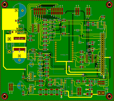
Below is a picture of the board layout. It is a two sided board using a combination of through hole (to use parts that I had in my parts box) and surface mount parts (for stuff that I had to get new). It uses the simplest design rules to keep the cost down. The backside of the board is a mostly a ground plane (the dark green is the back side).
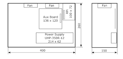
The front and side views (approximate) of the package is shown below. The space on the left is what I have left for future additions. When I decide where to put the speaker, I will update this picture. All dimensions are in millimeters (I grew up with the metric system through high school, had to learn the standard system in collage and in life, and now everything, at least in electronics, seems to be moving to metric - such is life).
The back panel is the busy part of this package and this is how I have it laid out. It will need some tuning after I build and test the circuit board. The part numbers for the circuit breaker and relay are shown on the drawing. the cutouts in the lower right corner are for the Raspberry Pi USB and Ethernet connectors. There is no need for the power connector since the Raspberry Pi will be fed through the GPIO connector. There is still a need for the two display connectors that I will need to make in the side of the enclosure.
I have been experimenting with cutting neat holes in the side and back panels. I have come to the conclusion that a combination of drill and file (idea from Jeff, J6JCA) and 15/16" Dremel cut off wheel. My experimentation on scrap metal suggests that the standard 1 1/4" wheel is too big.
This is the end of the design blog. The design is done and the parts that I did not have have been ordered and some have arrived. Any circuit that I had not built before (mainly the 5 volt switching regulator) have been prototyped and tested.
Once I am done with the build and test, I will add a second post describing my experience. Stay tuned.


